Contents
Introduction
On August 1st 2020, the frequency of the medium-wave transmitter was changed from 1476 kHz to 1485 kHz along with a number of technical changes. For this reason, the following article describes the situation before and after August 1st 2020.
The frequency was changed because since Easter 2020 OM Reinhard Pirnbacher, OE5TPM, opened his “Museum Radio” on this historical Austrian frequency. This frequency should not be interfered by the medium-wave transmitter JOE.
Technical explanations
Antenna
Before August 1st 2020
40 meter (131,23 feet) long stainless steel wire drawn diagonally across to just below the top of the tower.
At 1476 kHz this is about λ/5.
However, only a few wire windings at the base are sufficient to bring the wire into resonance at 1476 kHz:
After approx. 30 meters long but thick coaxial cable feed, which itself only attenuates by 0.4 dB, you get 13 dB reflection attenuation at 1476 kHz:
After compensation of the remaining inductive part with a 4.7 nF series capacitor at the transmitter output, the reflection attenuation improves to over 35 dB:
The metal frame of the flat roof with the widely branched lightning conductor network serves as a counterweight.
To protect against lightning strikes in the antenna wire, two additional lightning interception rods over 10 m high are installed.
After August 1st 2020
A minor change had to be made to the antenna system because a 5 m parabolic reflector was installed on the roof of the Institute building at the previous antenna base. The base is now about 5 m to the north-east, about 1.5 m from the edge of the roof. Because of the frequency change, the base loading coil visible next to the black insulator was reduced by one turn, so that the matching minimum was then 9 kHz higher.

Transmitter hardware
Before August 1st 2020
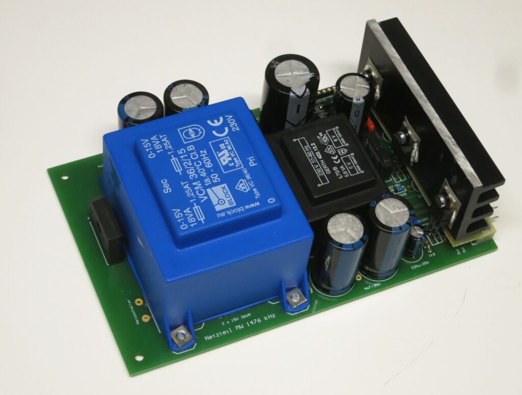
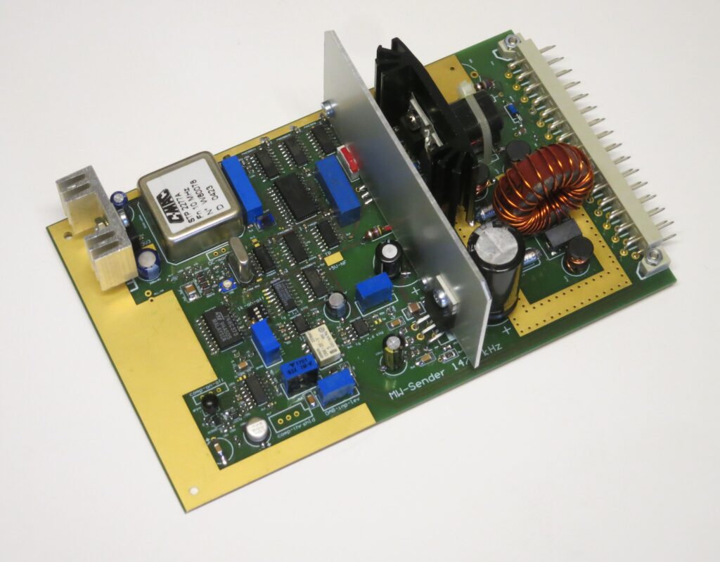
The transmitter consists of two “self-made” plug-in cards in Euro format
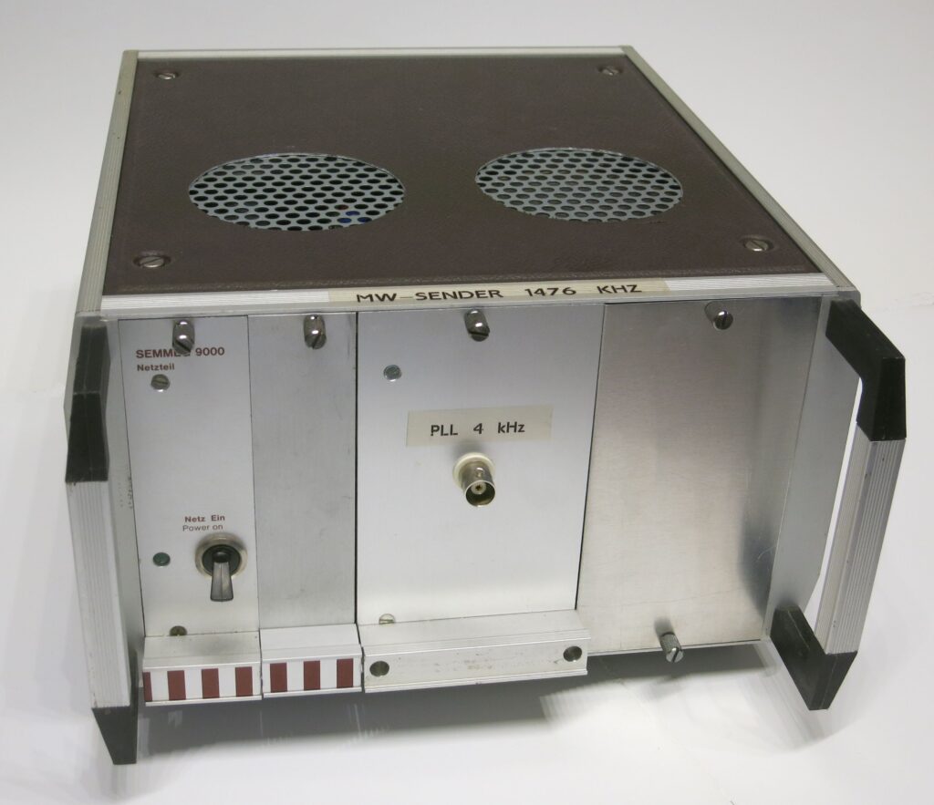
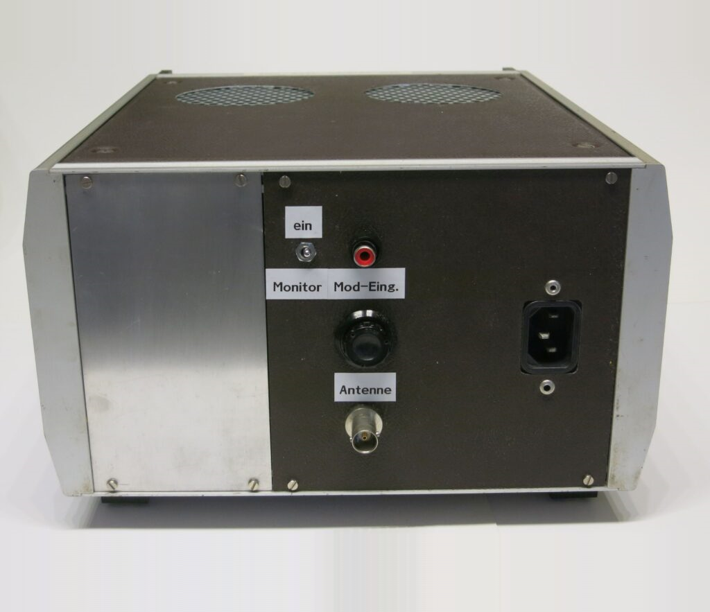
Power supply and transmitter unit with modulator (without modulation choke). The latter is housed separately in the aluminium housing, which accommodates the two plug-in cards.
After August 1st 2020
This is where most of the changes occur, because the transmitter can deliver far more power than before. Therefore, the more efficient pulse width modulation (PWM) is used instead of the standard AM by means of a drain choke. The RF power module including the PWM output stage originates from the former 100 kW transmitter Ismaning of the Bayrischer Rundfunk (built in 1995) and run on 801 kHz at that time. It can deliver 400 W carrier power (= 1.6 kW PEP) at 72 V supply voltage. Since only about 150 W carrier power had to be provided here, an inexpensive 48 V standard switching power supply (SMPS) could be used for the power supply. All individual modules are housed in a 19″ enclosure and can be seen in Fig. 2, with the exception of the power amplifier module, which is below the intermediate aluminium plate. You can see the 48 V SMPS at the top left, the filter PCB for the 48 V at the top right, the small-signal PCB (Eurocard) in the center right with the frequency processing and the generation of the modulation pulses for the PWM, and to the right the corresponding power supply unit with ±5V, 1 A each, also in Eurocard format. The toroidal transformer avoids complex µ-metal shielding for the suppression of 50 or 100 Hz spurious, which would otherwise arise via magnetic field coupling into the small-signal PCB of up to about -60 dBc.
PWM makes it very easy to control the RF power linearly by adjusting the AF amplitude and DC bias to the same extent with a common potentiometer. The two spiral potentiometers shown in picture 2 on top are exactly designed for this purpose. With one of them you can adjust the power from about 5 – 50 W, with the other one from 50 to 150 W. With the switch in between you can easily swap power levels between the two preset values “low power” and “high power”. Normally switching is time-controlled, from 6 a.m. – 6 p.m. “low power” and from 6 p.m. – 6 a.m. “high power”.

The RF power module underneath the intermediate aluminum plate has a balanced output of about 1.4 Ω. The downstream 1:6 balun with the pot core converts this into 50 Ω unbalanced. This is followed by a 6-pole low-pass filter (center left in the picture) with a zero in the last circuit on the third harmonic at 4455 kHz (the 2nd harmonic is strongly suppressed a priori by the square output voltage of the RF power module). This is followed by a -30 dB directional coupler (square PCB) for measuring the output power and monitoring the matching. The output stage is switched off for >25 W reflected power and in case of excess temperature.
The power amplifier is cooled by two small fans (on the far right of the picture underneath the white bar) which ventilate it like a horizontal chimney. The air outlet is on the left. The fan at the top (picture 3: grille to the left of the dummy load) cools the ferrite cores of the balun, output filter and directional coupler. All fans are temperature-controlled and normally run at a very low speed, i.e. they are hardly audible.

Frequency processing
Before August 1st 2020
For frequency processing, a commercially available 14.7456 MHz crystal is pulled to 14.76 MHz. A frequency division by 10 results in the desired 1476 kHz. A further frequency division by 369 results in 4 kHz. This frequency is the largest common divider of 1476 and 10000 kHz and is compared with a 10 MHz OCXO by PLL after division by 2500. The 1 kHz tone emitted during night is also derived from the 4 KHz by division, as is the sampling period (1024 ms on and off each).
After August 1st 2020
Because of the new frequency of 1485 kHz instead of 1476 kHz and the PWM, there are a few changes. As before, the crystal frequency (now 14.85 MHz) is divided by 10 to yield the final frequency. However, since 1476 kHz was still valid when the new transmitter was used, the final frequency can be divided either by 1485 or by 1476. The resulting 1 kHz is then locked to the frequency of the 10 MHz OCXO divided by 10,000 via PLL.
According to the manufacturer, a switching frequency between 73 and 90 kHz is required for the PWM. This needs to be in accordance to the low-pass filter on the output side, which then provides the continuously varying drain voltage from the AF pulses. For this purpose, the final frequency is divided by 18, which results in 82.5 kHz (formerly 82 kHz).
RF power amplifier
Before August 1st 2020
The 1476 kHz TTL signal directly drives the RF output stage: A push-pull switching amplifier with two MOSFETs and a push-pull transformer leads into a 5th order elliptical filter (Cauer filter) on the secondary side. For sufficient suppression the zeros of the filter response are located at the first unwanted harmonics. The filter is designed in such a way that in the event of a short or an open loop circuit at the output, no short circuit transforms into the MOSFETs, which could endanger them. Without modulation the MOSFETs are supplied with approx. +15 V DC which is provided by the modulation choke.
Modulator
Before August 1st 2020
The modulator is a standard audio IC with sufficient power headroom. It is operated with 36 V DC, so that 30 Vpp AF can be generated without distortion. This voltage is capacitively superimposed on the +15 V after the modulation choke at the MOSFETs, so that their supply voltage can vary between 0 and +30 V maximum, which results in 100% modulation degree. At the modulator input an 8-pole Cauer filter limits the modulation frequency to about 4.3 kHz. An upstream compressor allows the AF dynamic range to be reduced.
The on-board detector receiver with loudspeaker output placed directly on the PCB in the RF output area allows direct control of the transmitted modulated RF.
RF power amplifier and modulator
After August 1st 2020
This is a NAA25B module from Nautel. There are 2 x 4 IRF140 MOSFETs wired as a full-bridge switch (hence the balanced output) and two parallel IRF140s as switches in the PWM output stage. Of course, the MOSFETs are a bit outdated. With a more modern transistor, e.g. the BSC098N10NS5 from Infineon half the number MOSFETs would suffice. Switching would be much faster thus yielding a better efficiency. However, keep in mind that the frequency used here is almost twice as high as the former 801 kHz of the BR.

Basic technical data before August 1st 2020
| antenna | 40 meter long stainless steel wire |
| frequency | 1476 kHz, OCXO stabilized with drift of a few mHz |
| modulator | Push-pull AB amplifier with drain choke, up to 100% AM, limited to 4.5 kHz AF range. |
| transmitter amplifier | Push-pull switching amplifier, 8 W carrier power, 32 W PEP |
| monitor | on-board detector receiver with loudspeaker output |
Basic technical data after August 1st 2020
| antenna | 40 meter long stainless steel wire |
| frequency | 1485 kHz, OCXO stabilized with drift of a few mHz |
| modulator | Pulse width modulator with 82.5 kHz switching frequency |
| transmitter amplifier | Full bridge switching amplifier, max. 150 W carrier power, 600 W PEP. Power can be continuously adjusted from 5 – 150 W and quickly toggled between two levels. Max. efficiency approx. 70%. |
| monitor | on-board detector receiver with loudspeaker output |
Acknowledgement
Special thanks to “Das Rundfunkmuseum” in Cham. Its founder, Michael Heller, provided the BR power amplifier module and a test PCB for processing the PWM signal. Tilman Betz and Hans Schweiger provided exemplary support during the development as they had already designed the 1500 kHz transmitter for “Radio Eule” in the “Deutsches Museum”. This device works only 15 kHz higher using the same module so that both of them allready gained a lot of experience.
Brodcasting program
05 – 24 h: “Funklust – Deine Campusmedien”
00 – 05 h: periodically interrupted 1 kHz sine tone, 1024 ms off, 1024 ms on
All times are local time. Sporadic shutdowns of the transmitter or no modulation due to maintenance work are possible.
Possible options of the transmitter
The transmitting hardware allows a slow frequency shift of the carrier in the Hertz or sub-Hertz range (currently still deactivated) synchronized with the OCXO for better identification of the transmitter during DX experiments. In the long term, an improved processing of the modulation signal (compression and spectral filtering) is also conceivable.
The story of Joe: a medium wave transmitter is born
The trigger for my idea of an “own” small medium wave transmitter was primarily the successive shutdown of all German AM transmitters: First the short wave, then the long wave and finally the medium wave. But the motivation for such a station was not so much nostalgia but rather the realization that there was no easy way for people interested in radio technology, especially young people, to get to grips with this topic.
A long odyssey to the destination
After switching off the long wave on Dec 31st 2014, I contacted the KEF (Commission for the Determination of Financial Needs), which was mainly entrusted with the switching off of the AM transmitters. I was told that nowadays AM only had a “museum character”. This gave me hope that we would be able to keep at least one of our large transmitters alive and perhaps put it into operation on special events, similar to the historic SAQ machine transmitter in Grimeton, southern Sweden.
Destroyed hope
But unlike in Finland, for example, where the long wave transmitter Lahti was converted into a museum and the antenna towers were kept alive as a local landmark, or in Switzerland, where the antenna tower of the Beromuenster station was preserved and even a radio hiking trail was set up, we destroyed almost all of these landmarks in Germany. Finally, on March 2nd 2018, the two 360 m high antenna towers of the DLF in Mudau/Donebach (one of the highest buildings in Europe!) were blown up. Now this remainder of hope for a remaining AM transmitter with a museum character was gone.
An own transmitter?
By chance I heard about Bernd Schmid (DL2MFP), who had the frequency of 801 kHz reserved for a small museum transmitter at the radio museum in Wertingen near Augsburg. He was already on air on special events. Later I also heard about Michael Heller, head of the radio museum in Cham, who together with his team saved the BR transmitter formerly located in Munich-Ismaning for the museum and also transmitted sporadically on 801 kHz. I found out from both sites how to start such a small medium wave transmitter. However, I also realized very quickly that the way was very hard – without any guarantee of ever reaching the goal.
First steps, first setbacks
Since I didn’t have a museum in my background, I first tried to arouse interest in my project through the large DARC association, to which I belong since 1972, primarily for the purpose of promoting young talents. But there other things were obviously much more important, my E-Mail inquiries were answered only after months (after renewed inquiry), but without recognizable enthusiasm. Although they regretted the shutdown, this was the only “activity” on the part of the DARC.
Another idea was to win over the major corporation Siemens (my long-term employer in Erlangen) for this project, especially as Siemens is currently building a new campus here for many millions of Euros. But here, too, there was no support. The expressed “understanding”, but when you’re ultimately referred from one department to the next, you know what’s between the lines. Another timid attempt at BR at the Dillberg broadcasting location was unfortunately just as unsuccessful, although some of the other employee would have liked to support it there. But there were clear guidelines from there bosses.
Positive turnaround on New Year’s Day
I had been in contact with the Fraunhofer Institute for Integrated Circuits (IIS) in Erlangen Tennenlohe many years before. I know the director, Prof. Albrecht Heuberger, personally for a long time. This personal contact should ultimately lead to success. He invited me to his apartment on New Year’s Day 2018 and had an open ear for the idea of a MW transmitter – not for museum reasons, but for educational reasons. Since the IIS has been broadcasting test broadcasts on MW and SW in DRM and later also in DAB+ for quite some time, I was in good hands.
Cooperation with Funklust Campus-Radio
Now one thing led to another: For these broadcasts there is already a radio program, namely the one of Funklust association and the required media license. The association agreed that I could also broadcast this program on MW later. For this purpose the media license was adapted accordingly.
Search for a suitable frequency
The application for a desired frequency at the BNetzA is then only a formality (i.e. with an existing media license). For this purpose I had been searching for free gaps in the MW band by waterfall diagram for months. The goal was a gap at the upper band limit because of a shorter antenna length and a better chance of sky wave propagation. In addition this gap that should be free in the evening hours. The frequency 1476 kHz seemed perfect and was applied for.
Unfortunately, I could not know that shortly after my broadcast permit was granted, a British MW radio station with far higher power also chose this frequency.
Happy end: the perfect broadcasting location
The biggest problems “media license, radio license and program design” were apparently solved, but the IIS was also able to offer a dream solution for the next two larger problem areas “antenna” and “accommodation for the transmitter”: A concrete tower almost 60 meters high with various other antennas stands directly next to the institute buildings and can be used for the MW-station as well.
In addition, there is the amateur radio club station DK0FHG in the attic of one of the buildings. The responsible radio amateurs welcomed my medium wave transmitter as a permanent guest.
The author
Ralph Oppelt (DL2NDO) is founder and developer of the medium wave transmitter Joe on 1476 kHz.
QSL-Cards
Selected QSL cards and reports are published here to give an impression of the station’s range.
QSL-contact
QSL cards can be requested via mw-joe@iis.fraunhofer.de by submitting a report.


